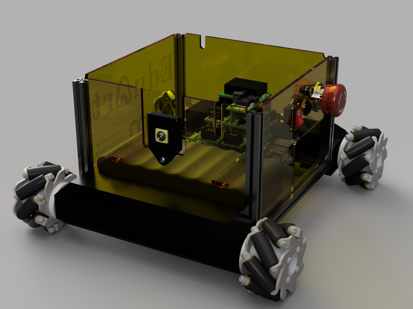
Base Assembly
This section shows step by step how to build the base of the EduArt MiniBot.
Step 1:
Assemble of the frame base.
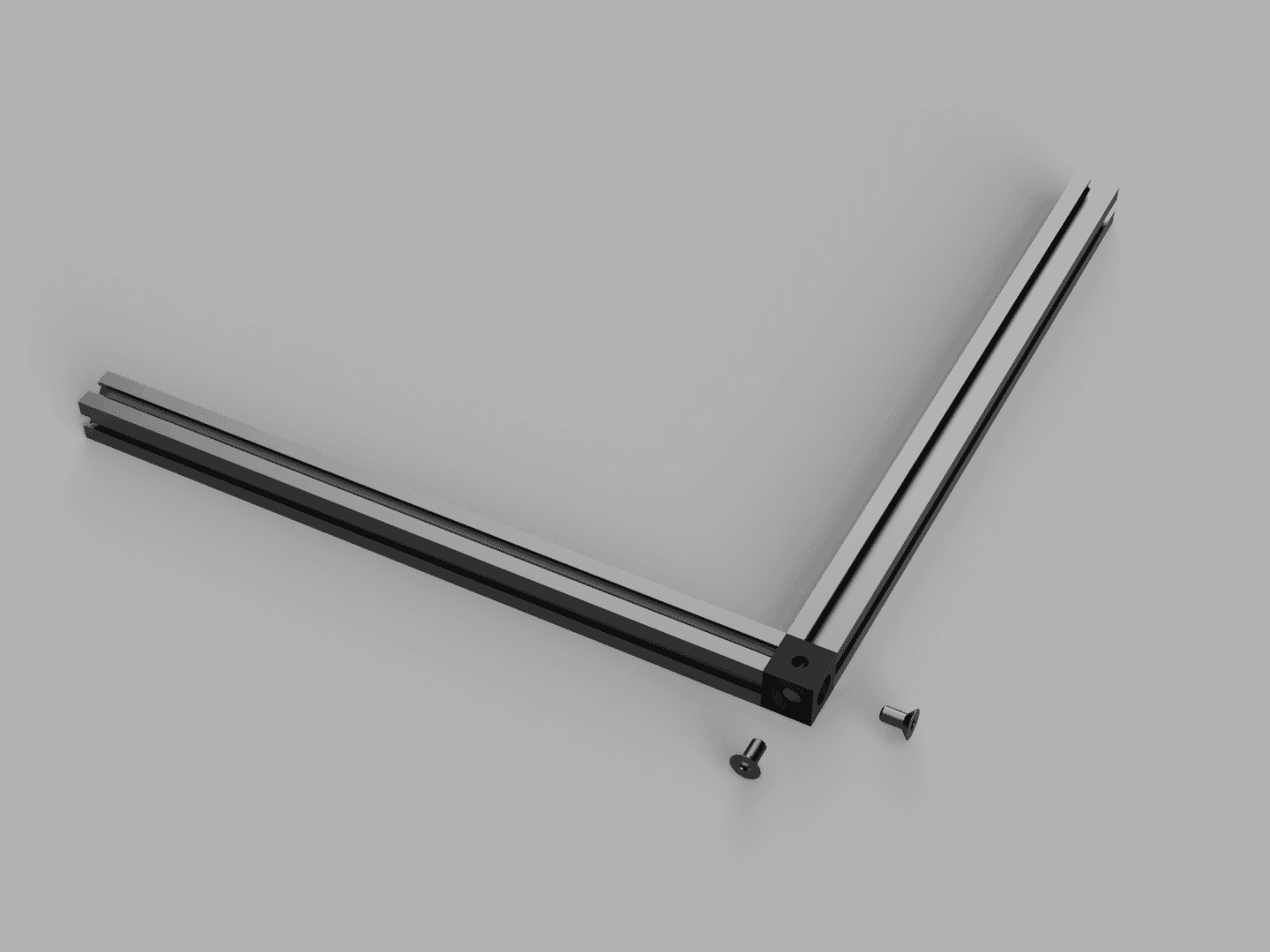
Connect two of the 150mm MakeBeams with a corner cube and two countersunk screws.
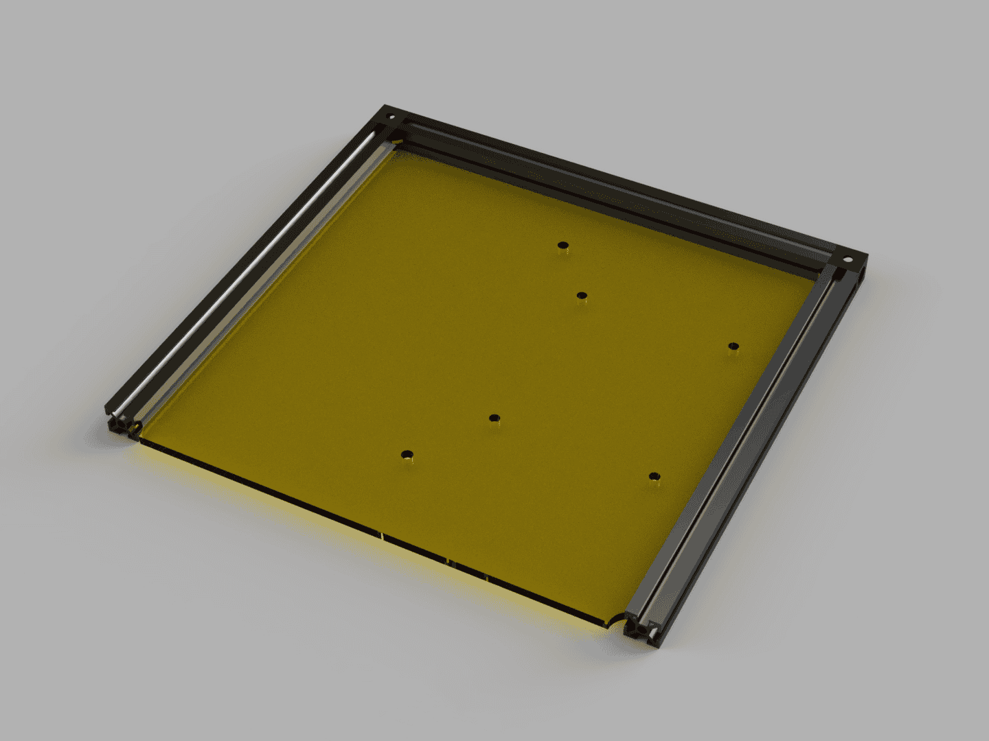
Then attach a third 150mm MakerBeam with a second corner cube and insert the bottom plate. The bottom plate determines the future orientation of the MiniBot. The holes closest to the MakerBeam will be at the back.
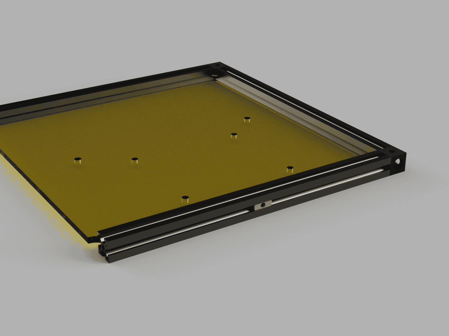 | 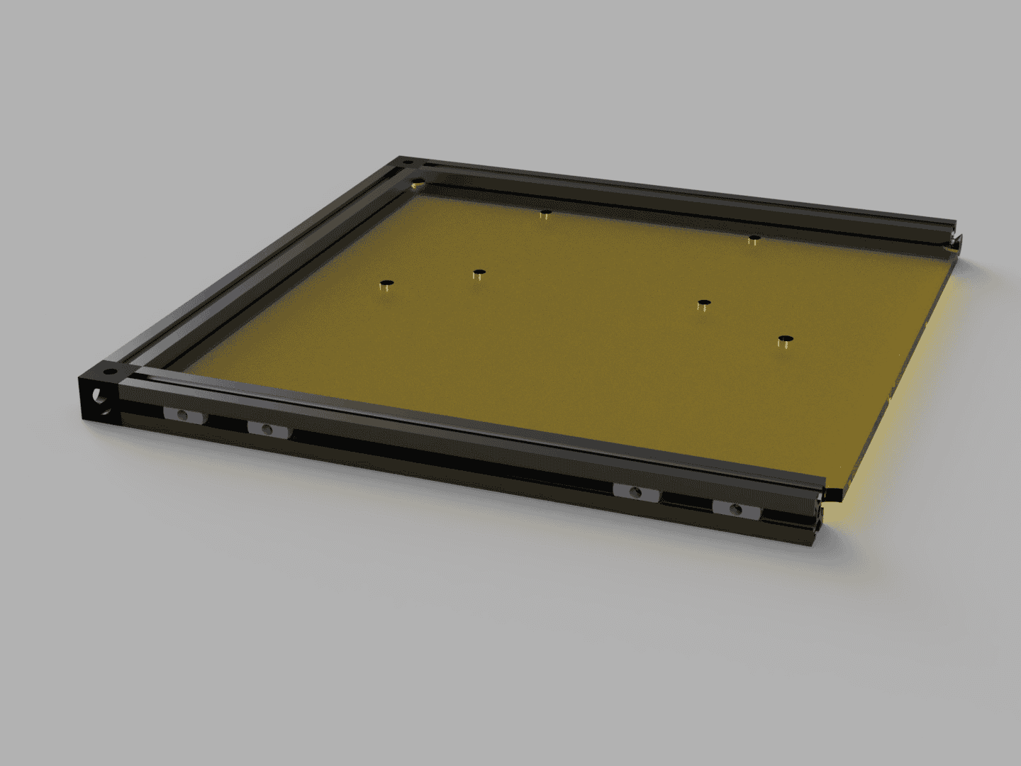 |
Insert 1 T-slot nut in the MakerBeam at the back. As shown in picture above. And insert 4 T-slot nuts in the front MakerBeam.
After that install the forth 150mm MakerBeam with 2 further corner cubes so that the bottom plate is fully enclosed by the beams.
Step 2:
Attaching the Motors.
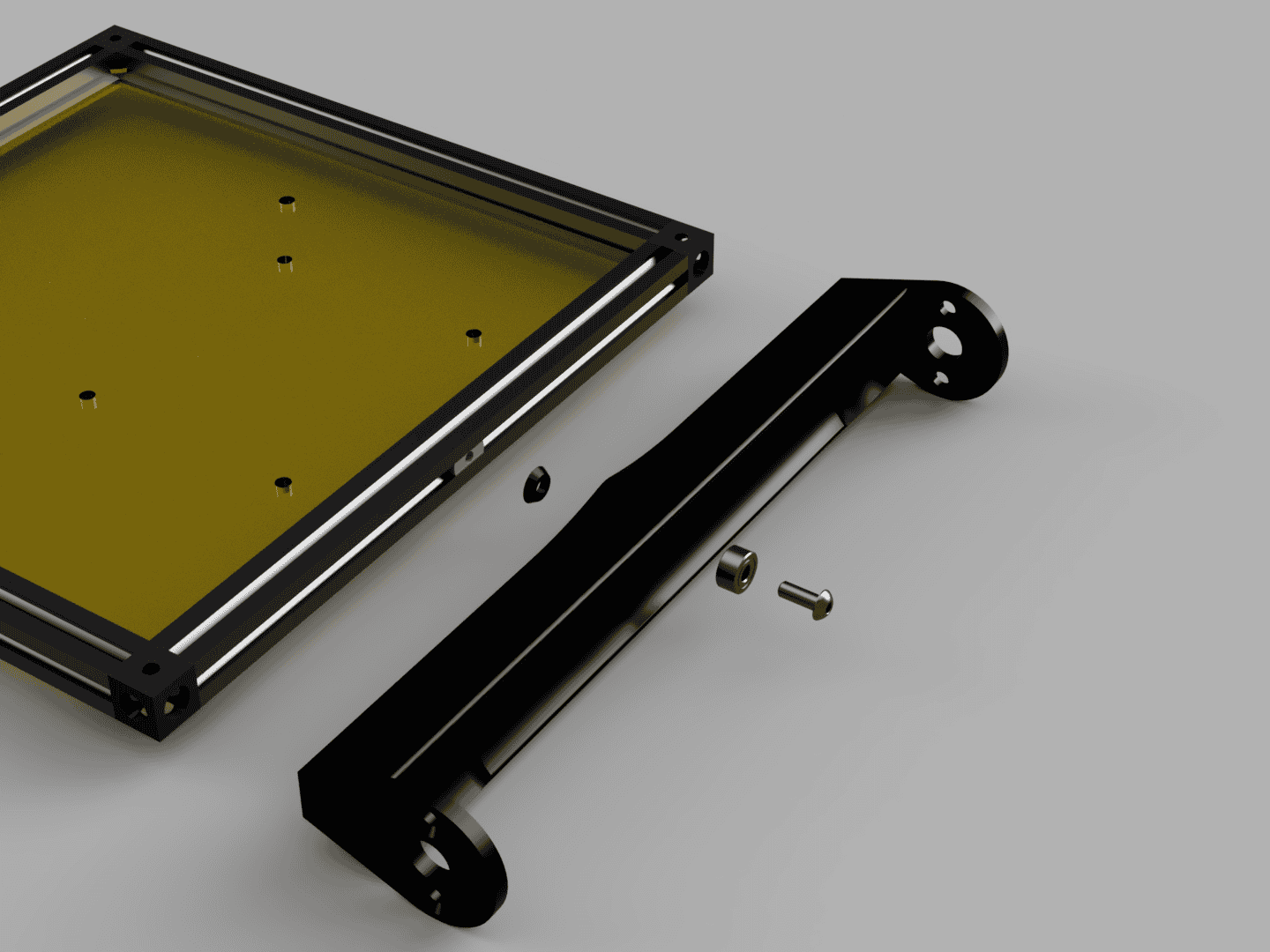
Insert the ball bearing in to the Rear Motor Mount. Attach the Rear Motor Mount to the back of the frame with a M3x8 round head screw and the Rear Motor Mount Washer. The Rear Motor Mount should rotate freely but have as little play as possible.
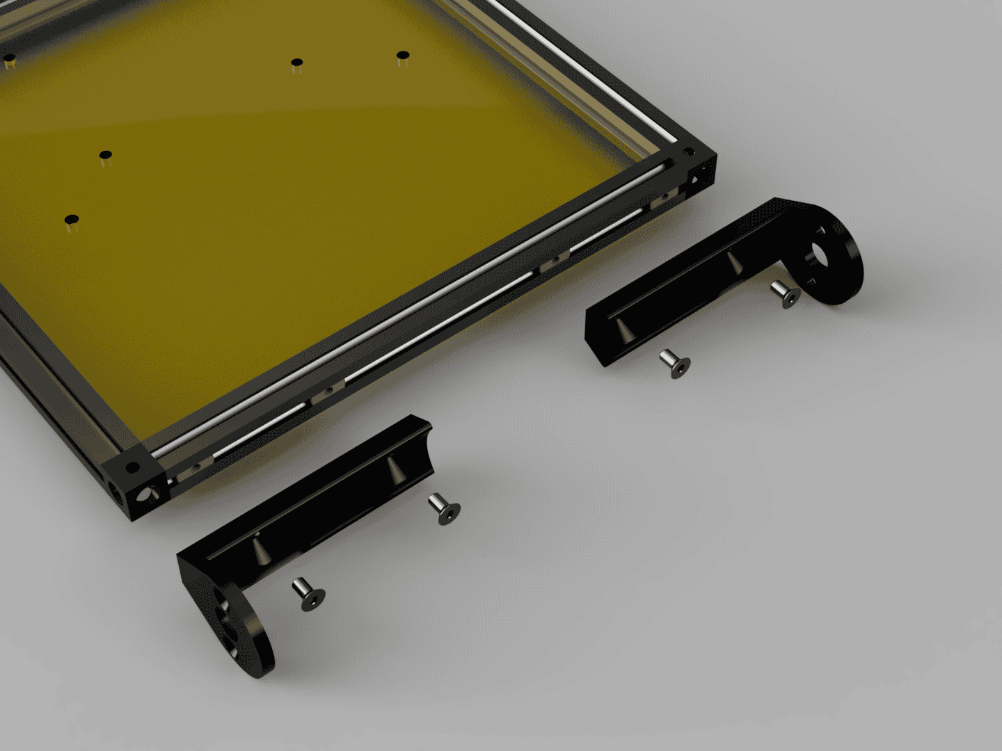
Attach the 2 Front Motor Mounts with 4 M3x6 countersunk head screws to the front MakerBeam.
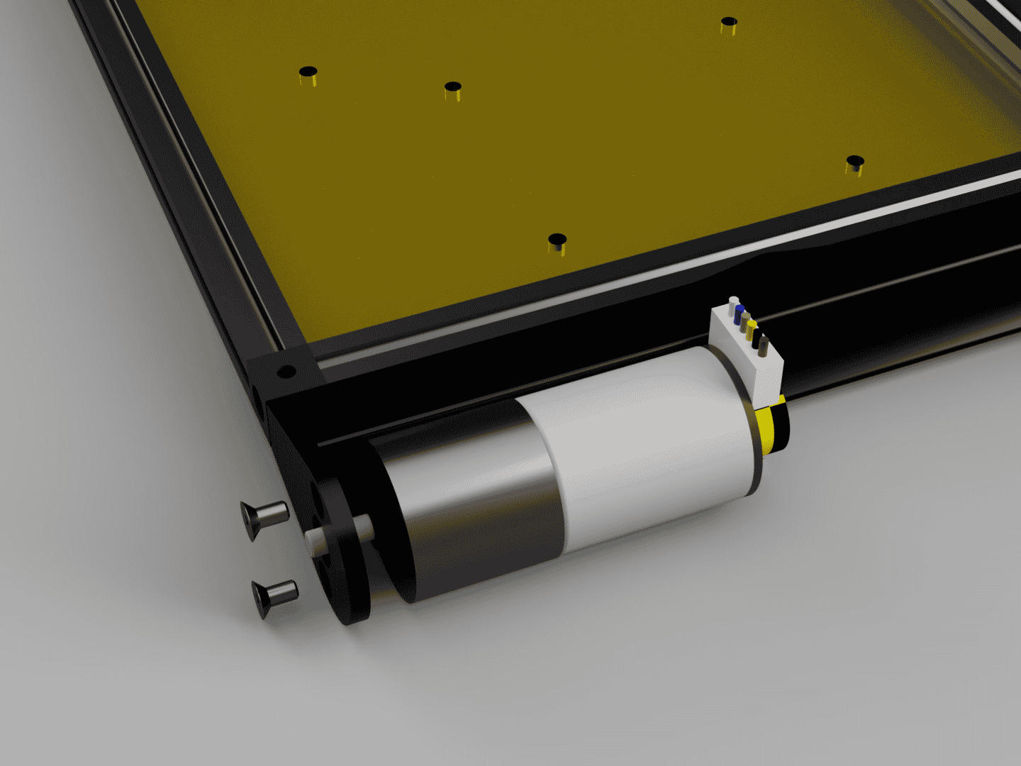 | 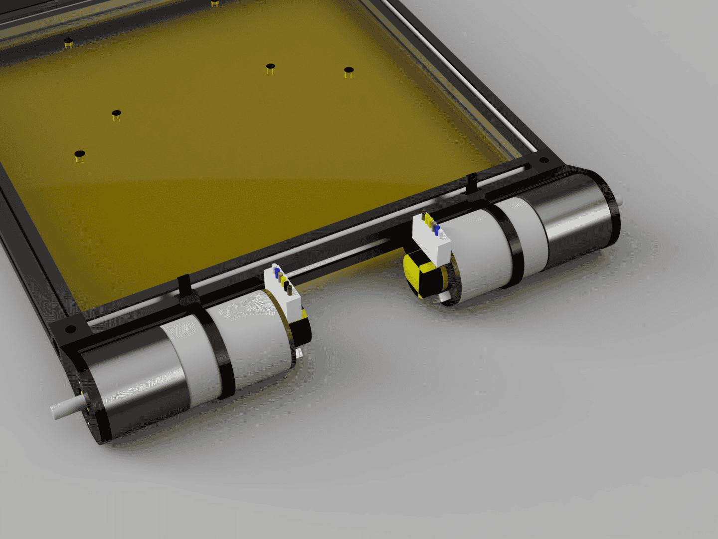 |
Attach the four Motors with 8 M3x6 countersunk head screws to the corresponding motor mounts and then secure each motor with a zip tie to the motor mount through the channels in the motor mounts.
Step 3:
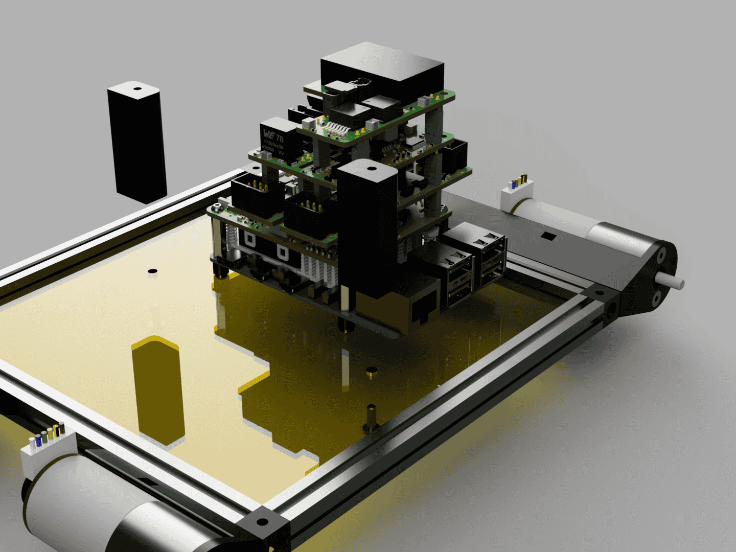
Stack Assembly.
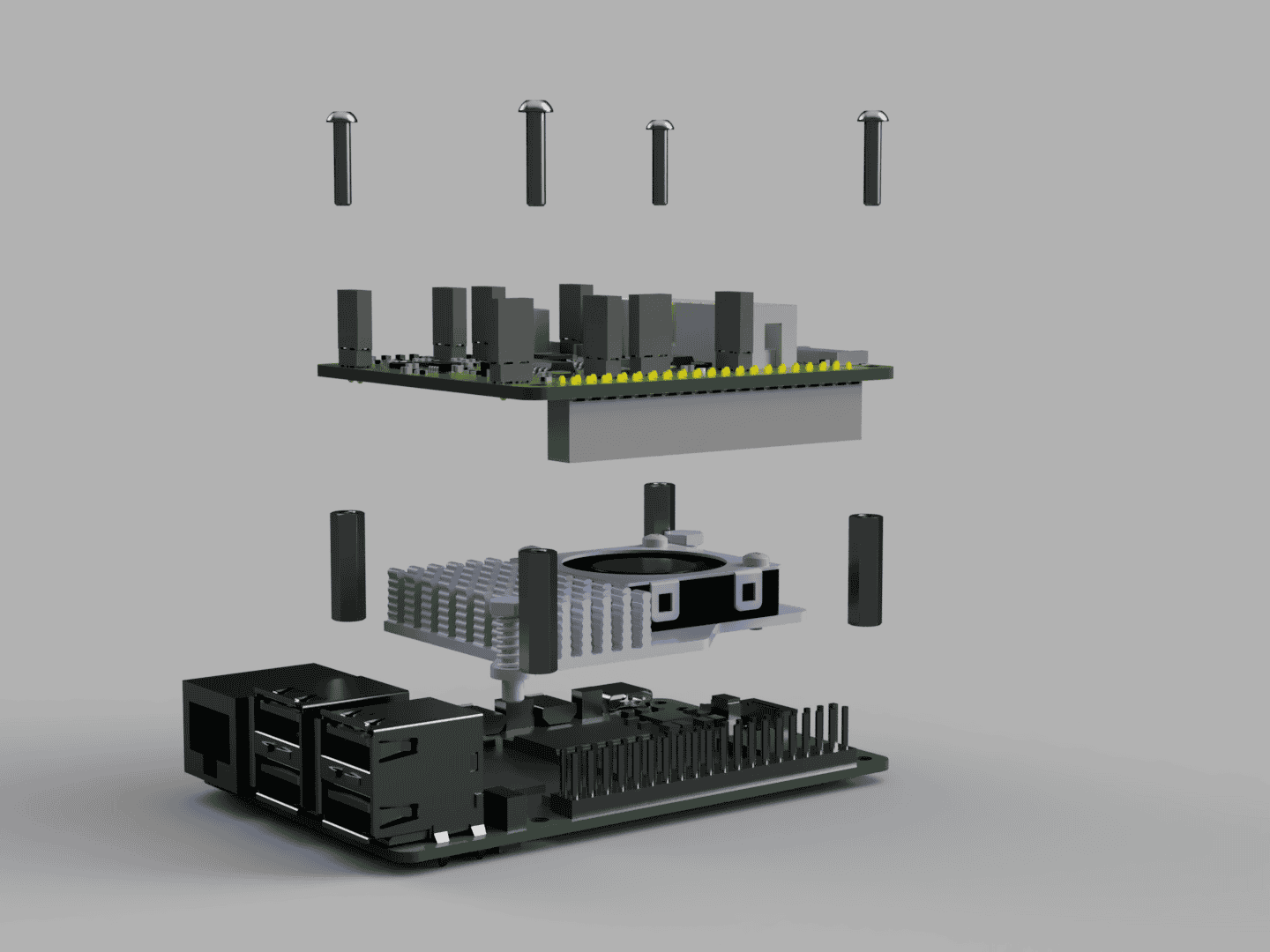
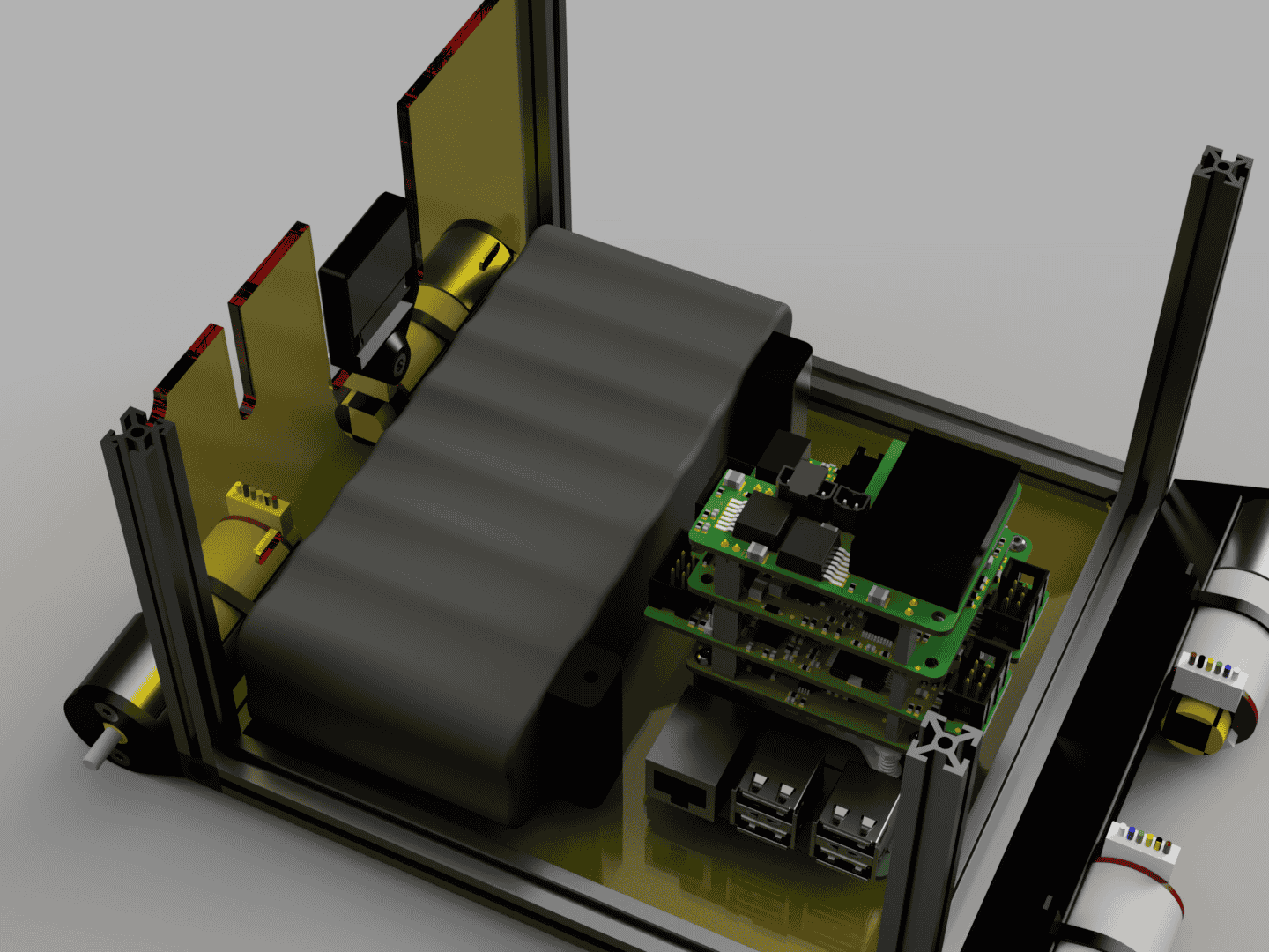
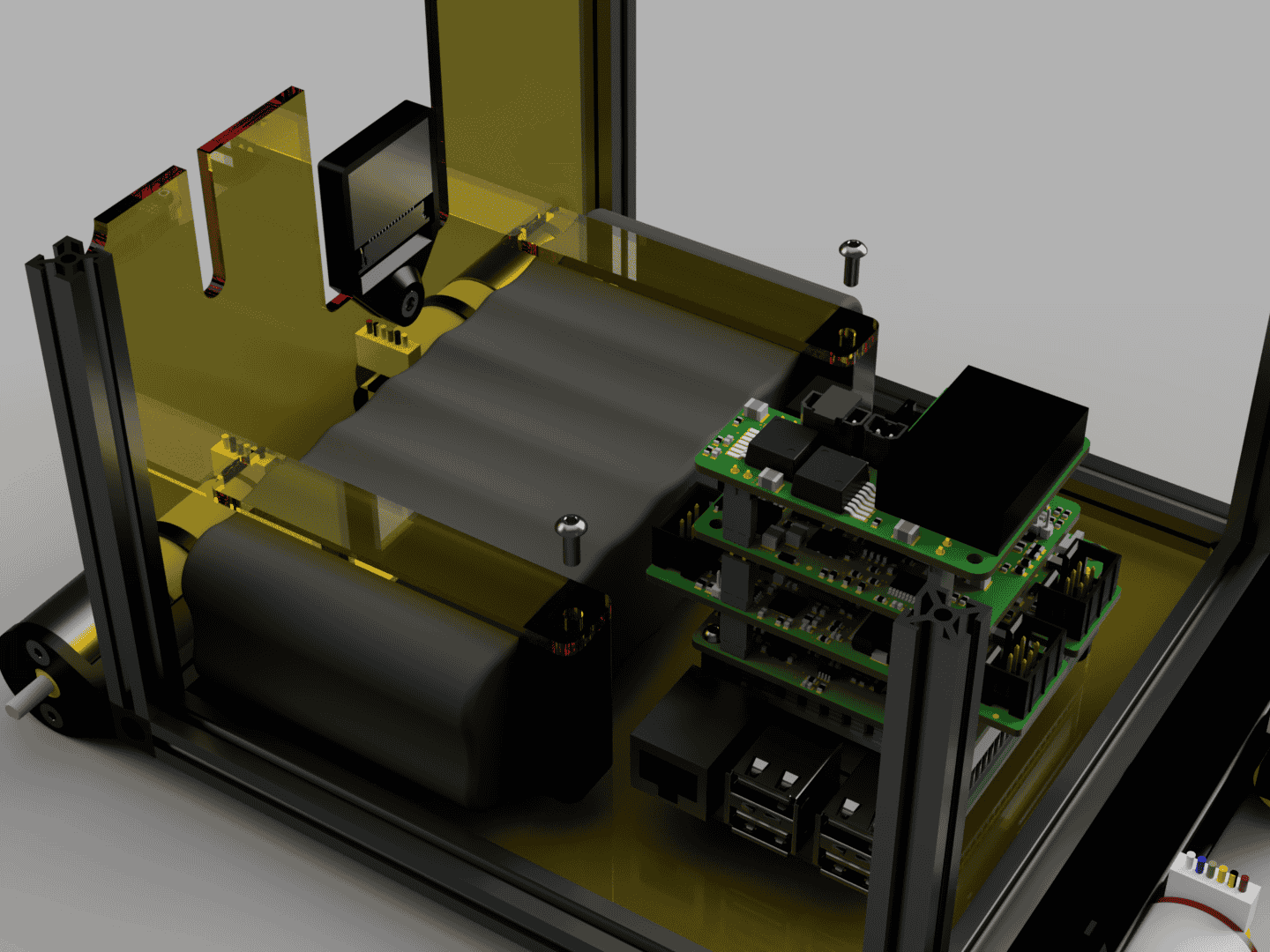
First attach the Raspberry Pi5 Cooler to the Raspberry Pi. Make sure the SD card is installed and has the correct operating packet installed. Later access can require disassembly. Screw the M2.5x16 standoffs to the EduArt Adapter Board with M2.5x12 round head screws. Connect the Raspberry Pi camera ribbon cable, it will have to be fed through all the attached boards. Then attach the EduArt Adapter Board to the Raspberry Pi via the header pins.
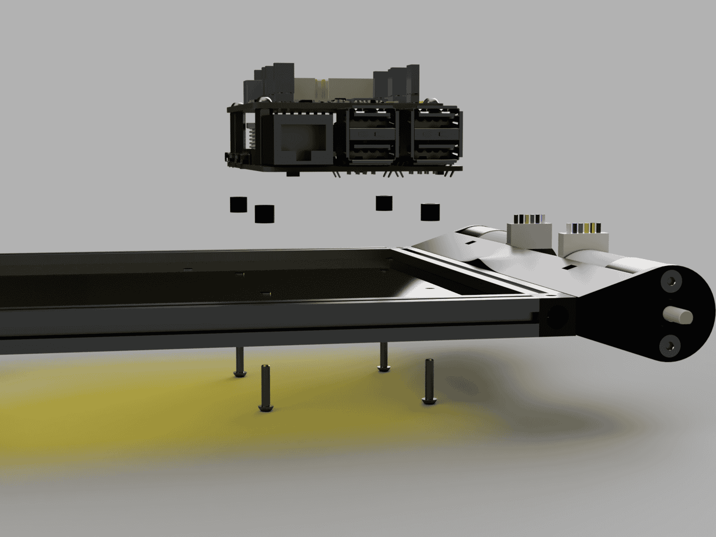
Attach the stack to the frame base with 4 M2.5x12 round head screws through the Raspberry Pi Spacers.
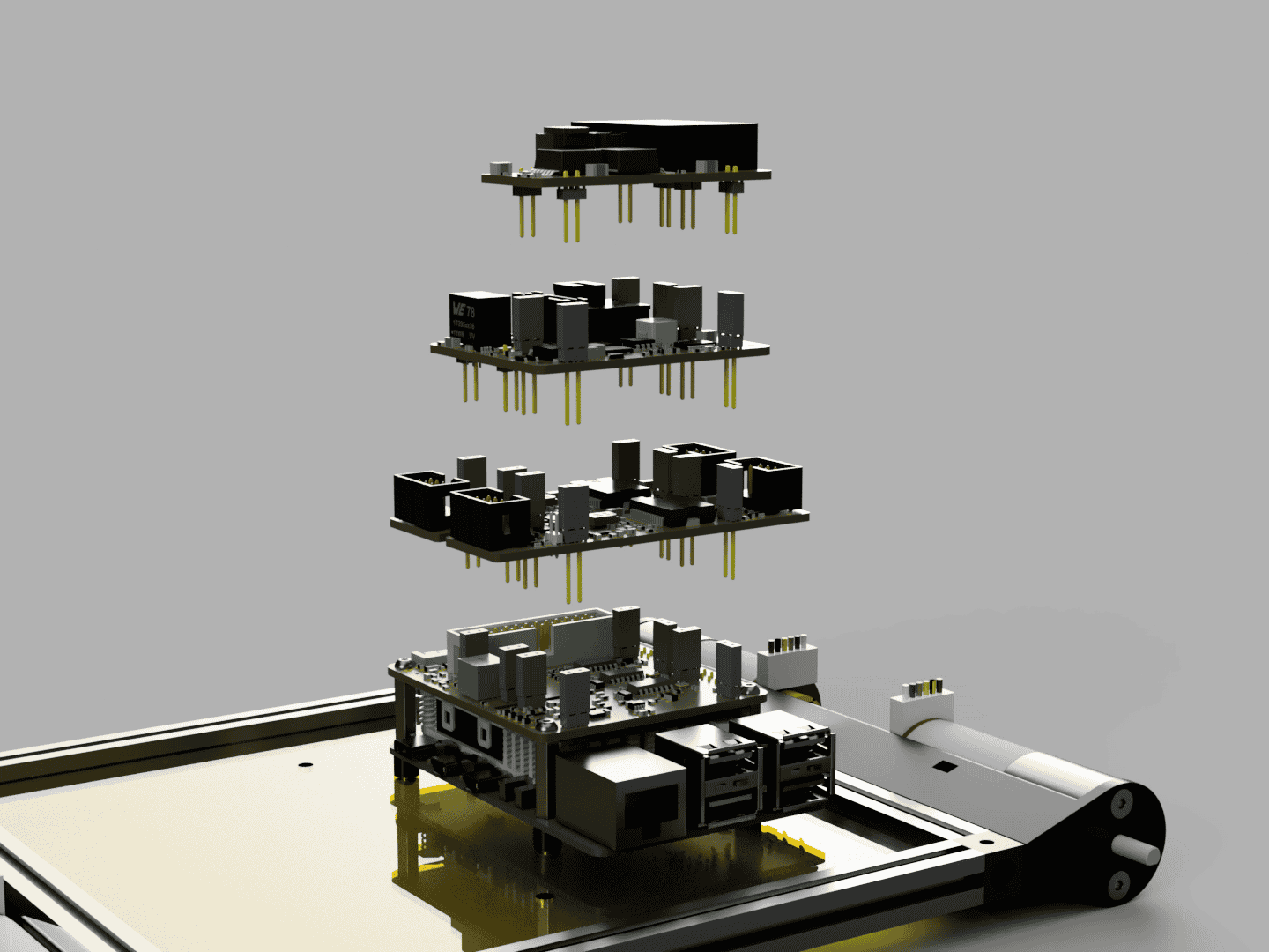
Attach the other EduArt Boards on top of the EduArt Adapter Board in the following order and feed the Raspberry Pi Camera Ribbon Cable through them. Two EduArt Motor Controller Boards side by side. On top of those the EduArt Power Management Module and the last one is the EduArt Auxiliary Power Module.
Step 4:
Attach the Battery Holders with 2x M3x8 to the bottom plate.
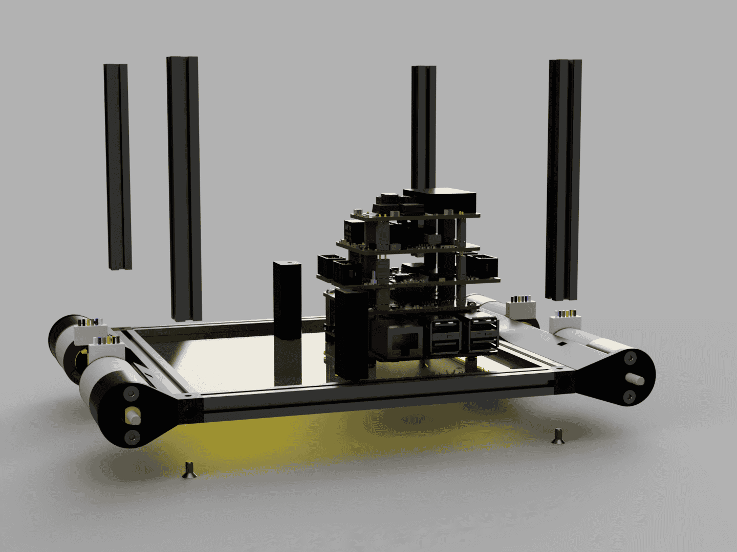
Attach 4 100mm MakerBeams with M3x6 countersunk head screws to the corners of the base.
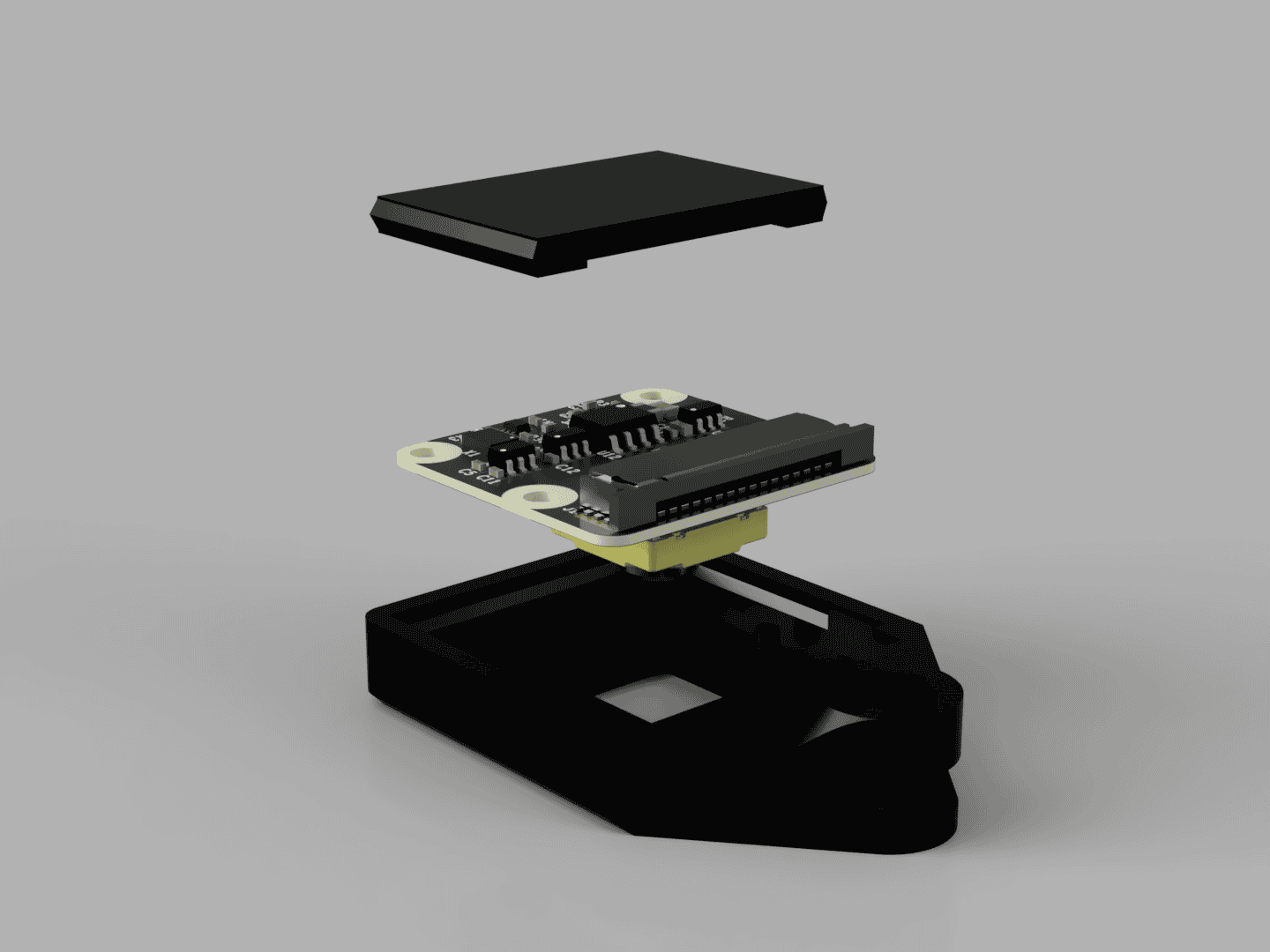
Place the Raspberry Pi Camera inside Raspberry Pi Camera Mount.
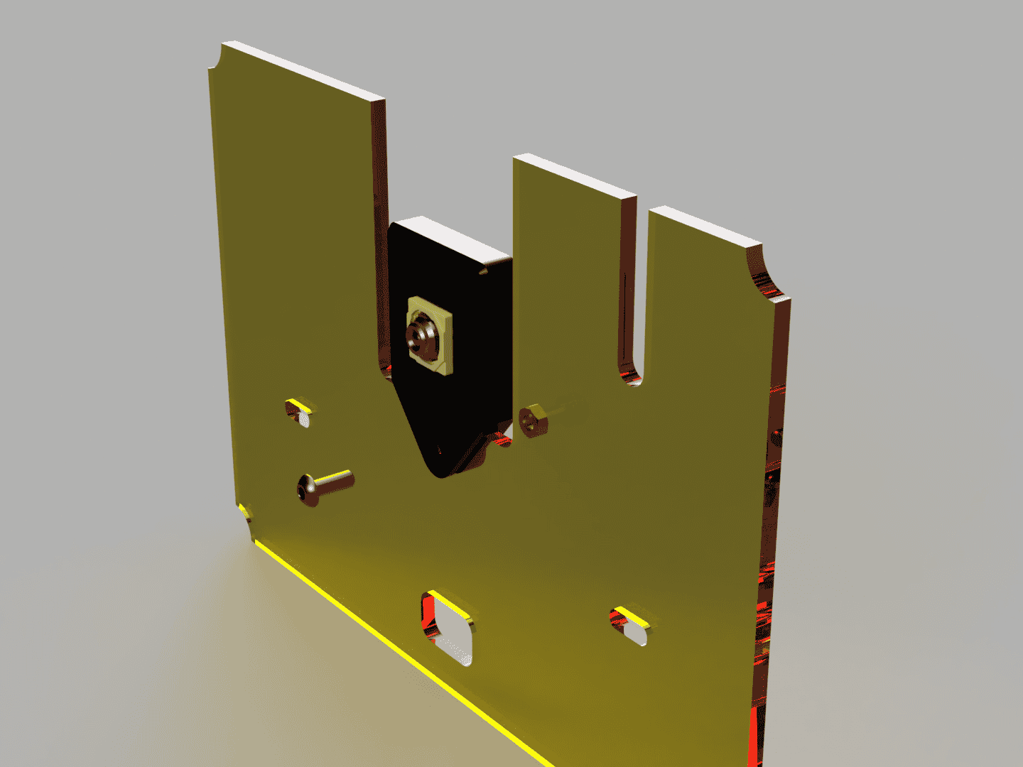
Screw the Raspberry Pi Camera to the front plate with a M3x8 round head screw and a M3 nut.
Place the Battery between the Battery Holder and the front MakerBeam.
Place the Battery Clamps on top of the Battery and in the cutouts in the front plate. Secure the Battery Clamps with M3x8 round head screws to the Battery Holders.
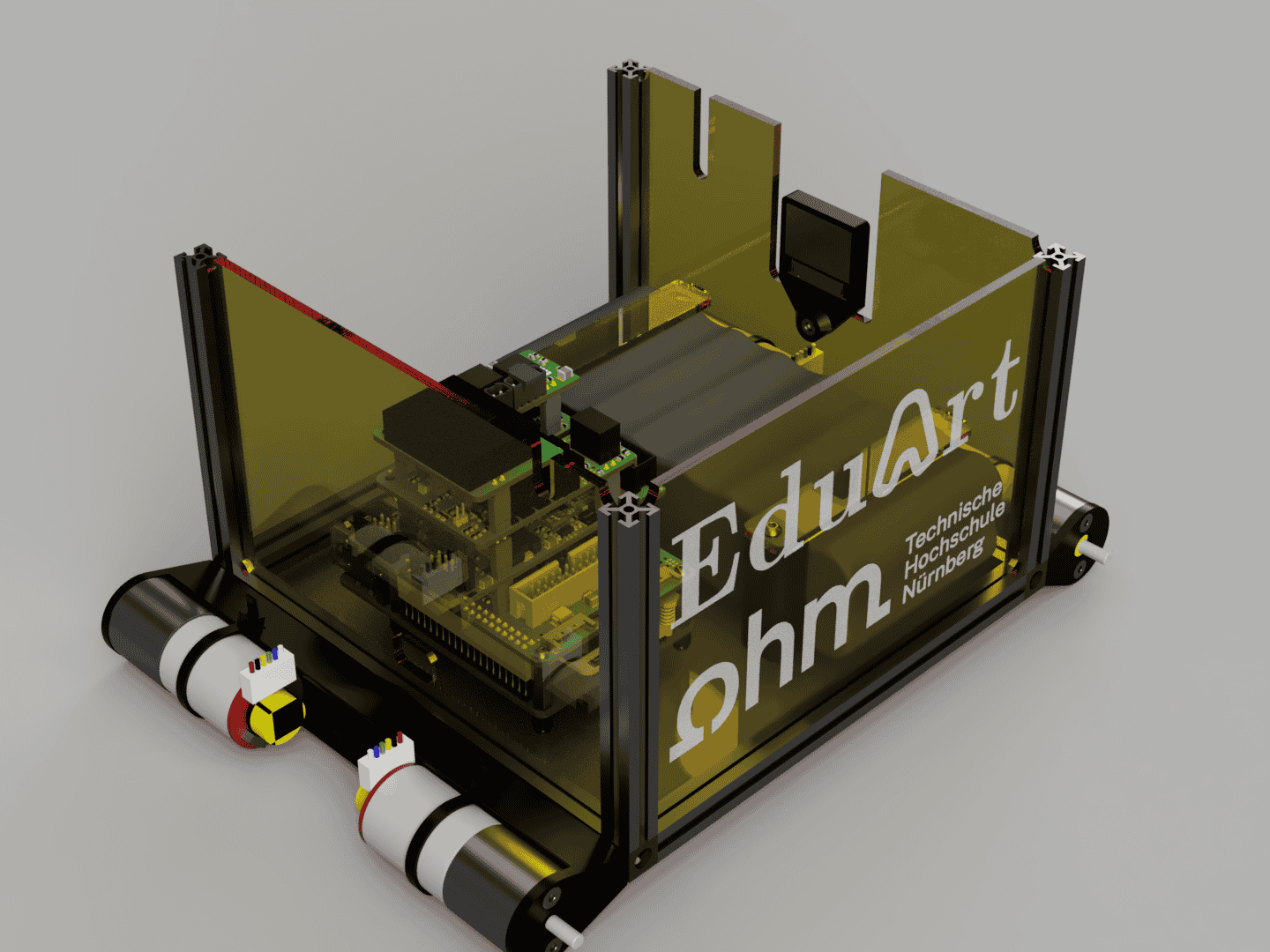
Insert the Side Plate Right and the Side Plate Back between the MakerBeams at the corresponding positions.
Step 5:
Preparing and installing the wiring.
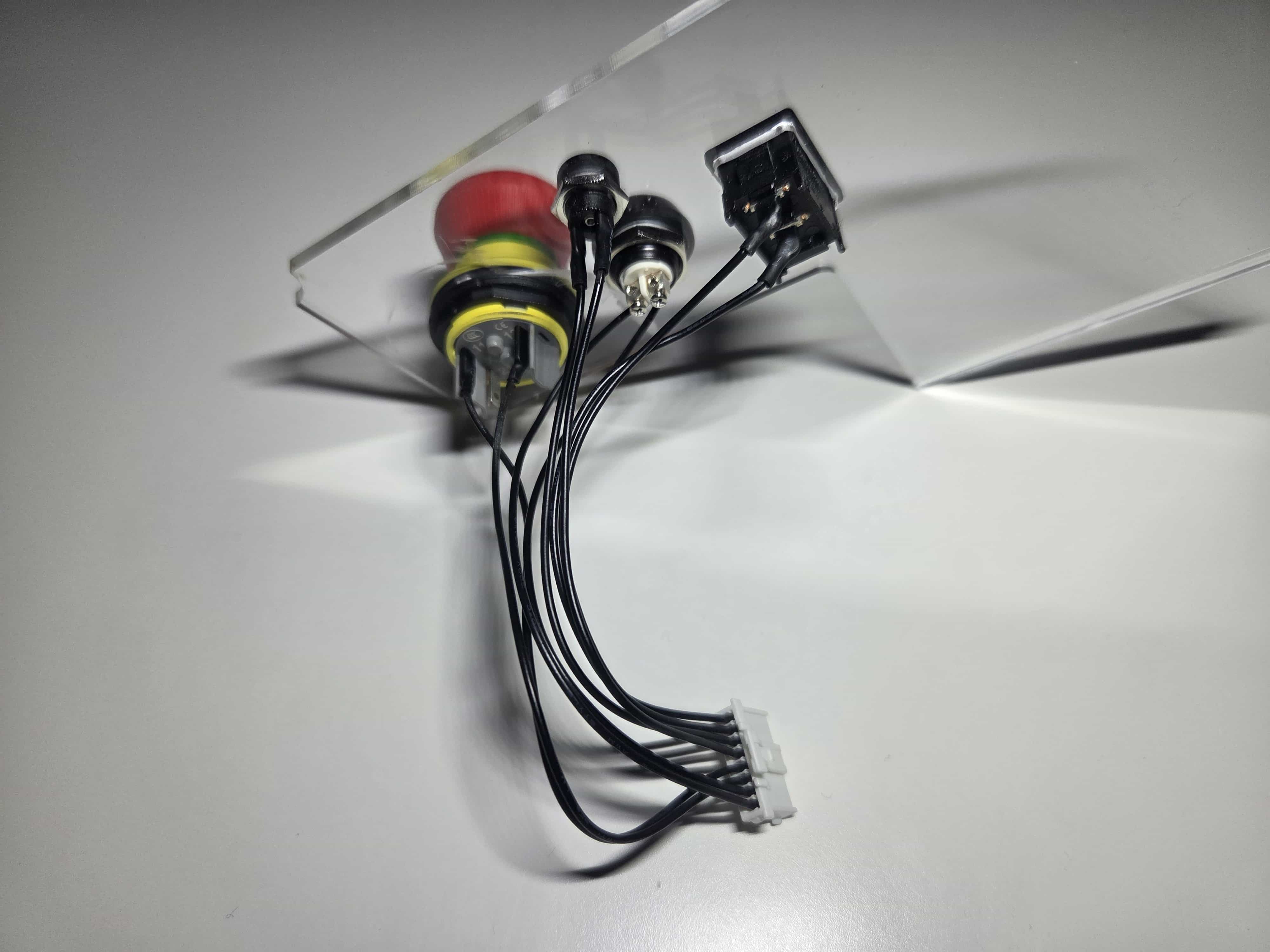 | 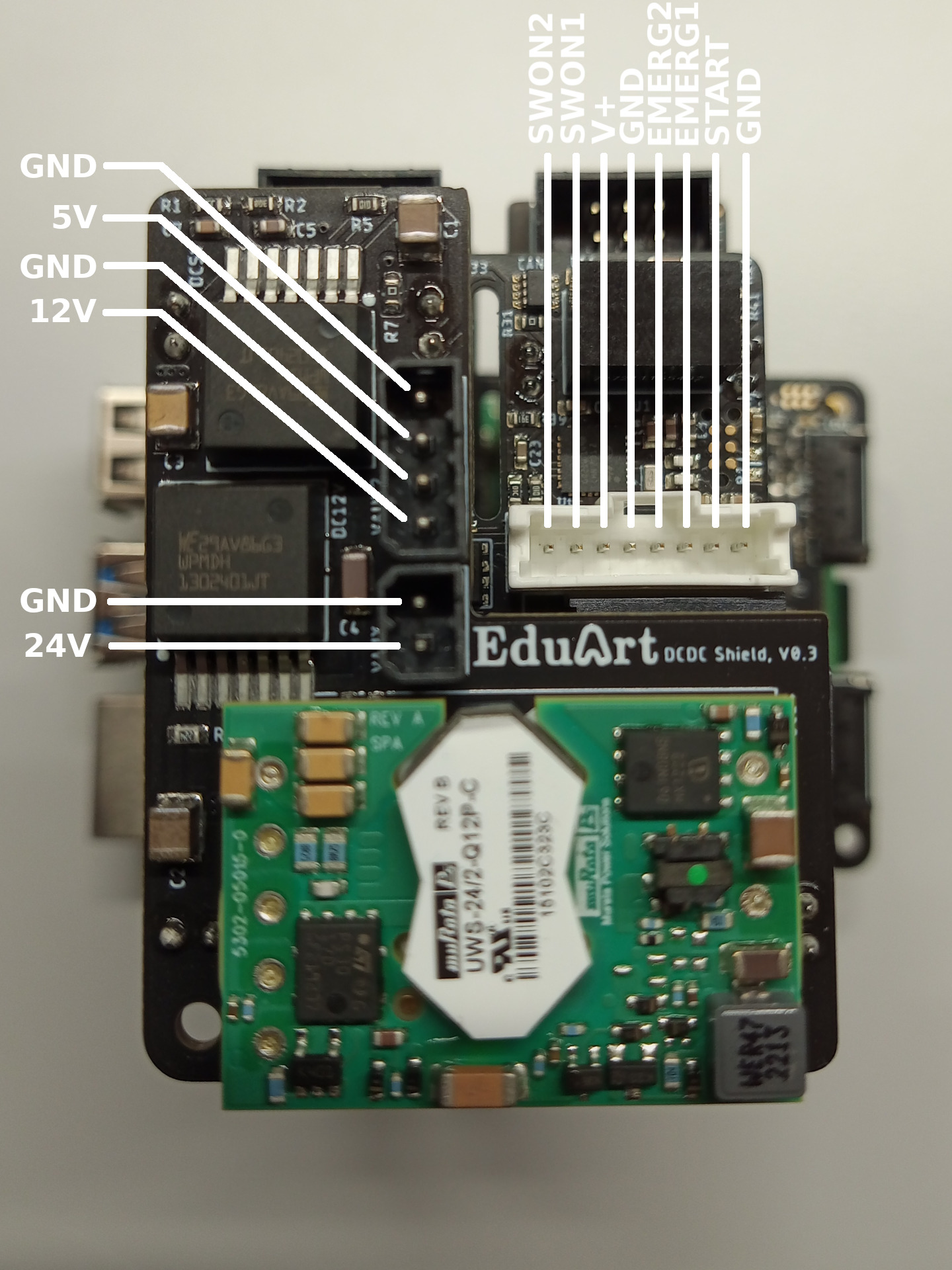 |
Install the switches in to the Side Plate Left and solder them to the correct positions on the connector that connects to the EduArt Power Supply Module.
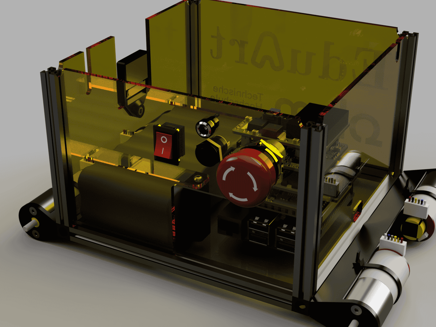
Install the Side Plate Left with the switches to the corresponding position between the MakerBeams.
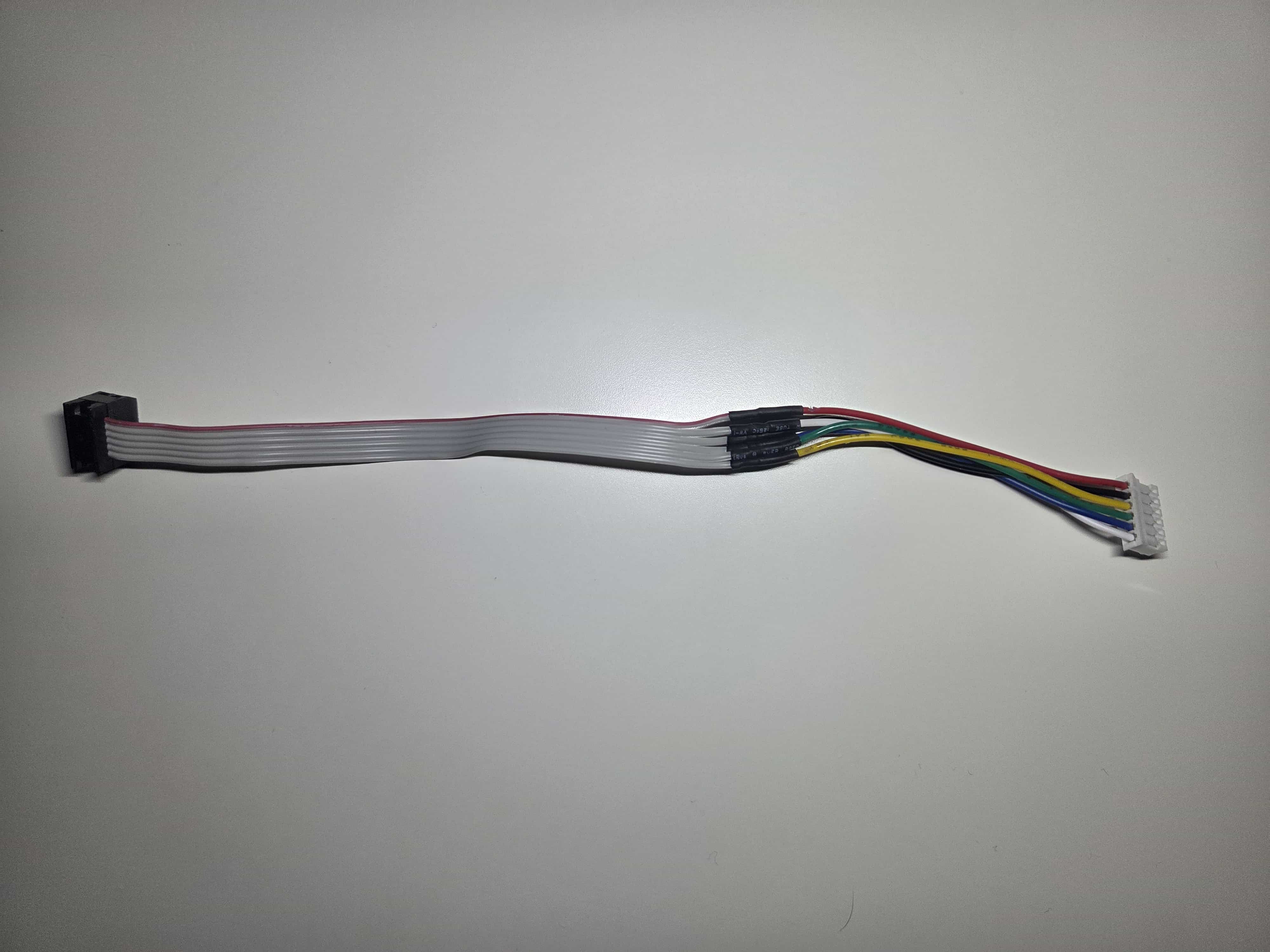
Solder the motor cables to the cables needed for the EduArt Motor Driver connectors.
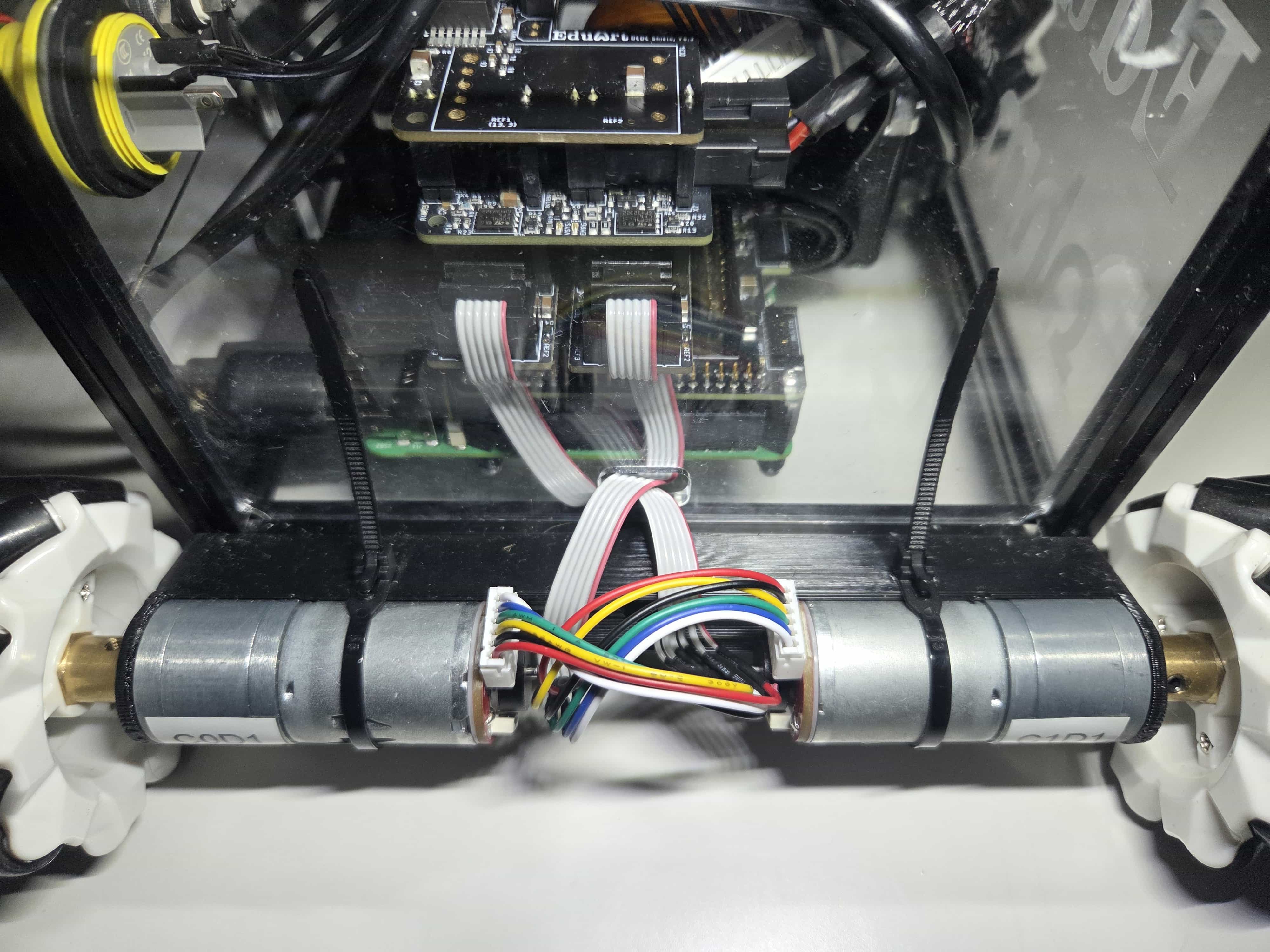
Connect the motors to the EduArt Motor Controllers with the cables by feeding them through the corresponding opening in the front and back plates.
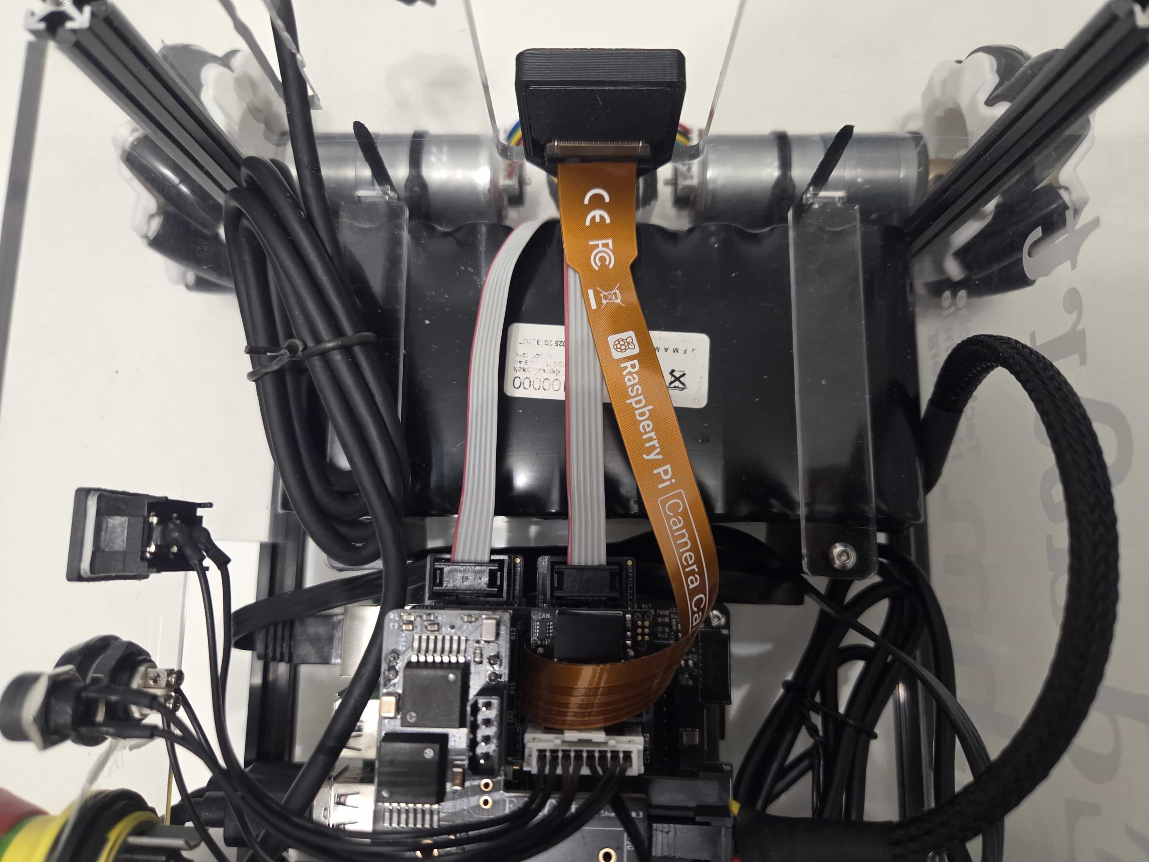
Connect the Raspberry Pi Camera Ribbon Cable to the Raspberry Pi Camera.
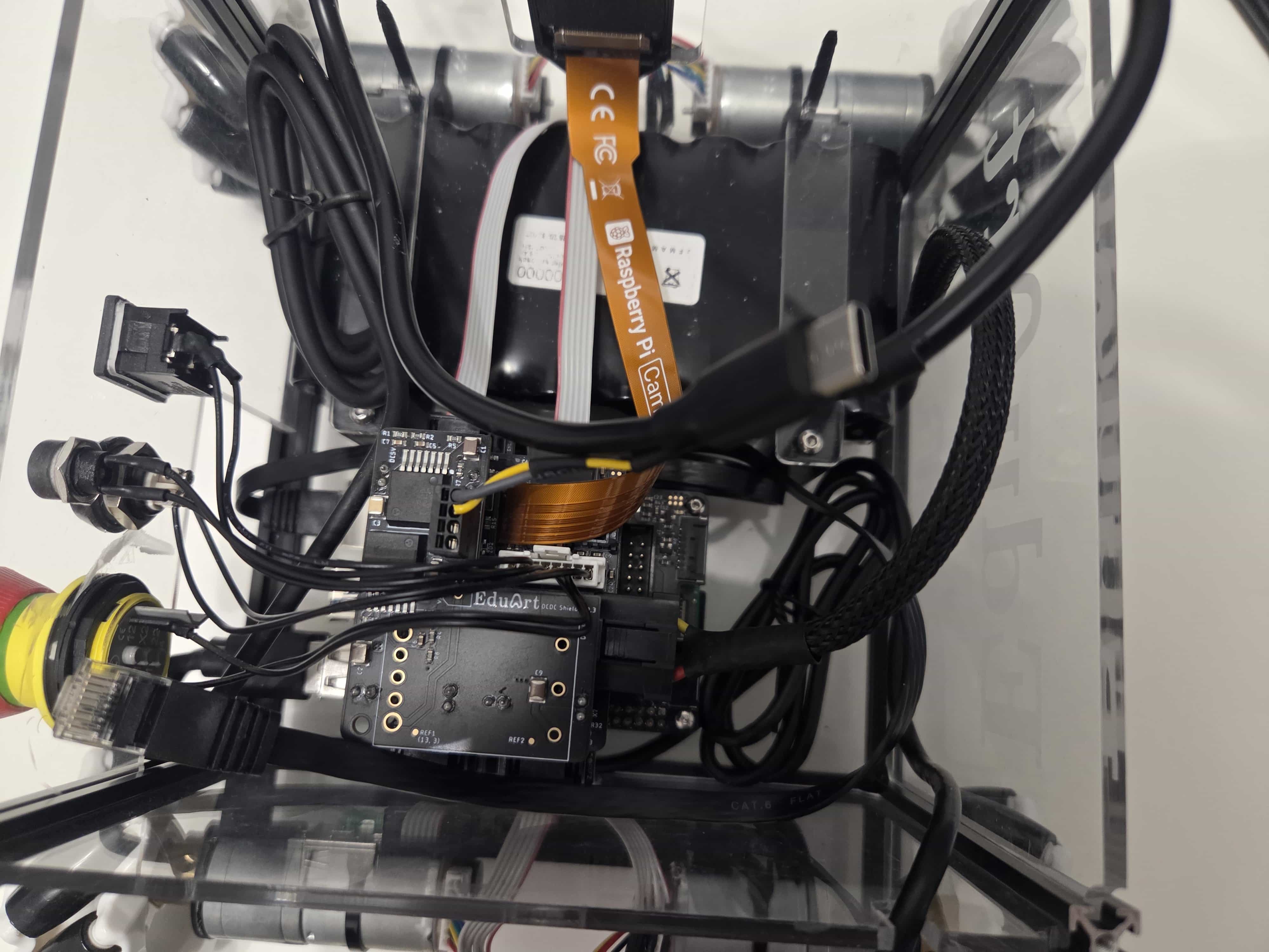
Connect the 5V to USB C Router Cable to the header on the EduArt Auxiliary Power Module.
Connect the Ethernet and lidar cables to the Raspberry Pi and just let them rest inside the base for now.
Step 6:
Finalizing the Base Assembly.
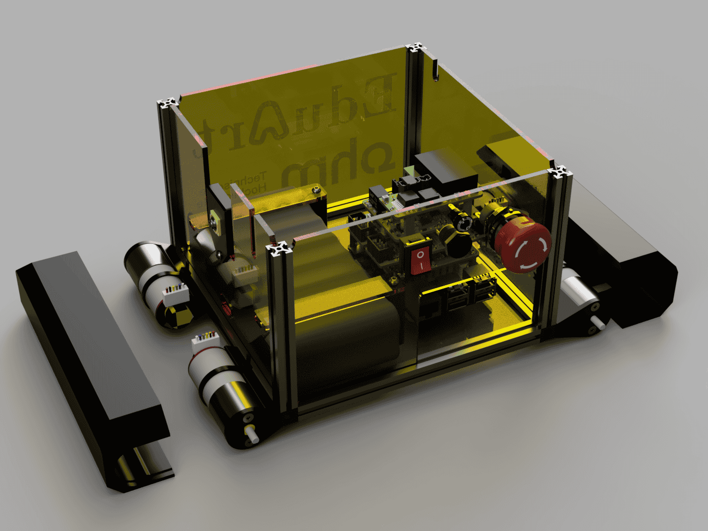
Attach the Motor Covers Front and Back on to the motors.
Finally attach the mecanum wheels to the motors.